
AGV Gearbox: Size the Drive, Compare the Layout
Estimate wheel torque, ratio and bearing loads, then check the evidence and trade-offs before requesting a gearbox.
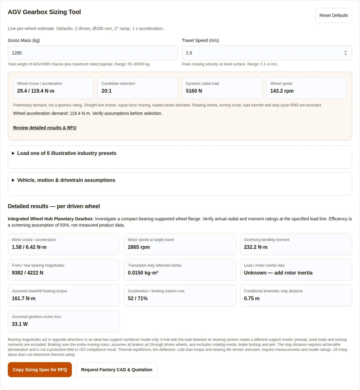
AGV Gearbox Sizing Tool
Live per-wheel estimate. Defaults: 2 drives, Ø200 mm, 2° ramp, 1 s acceleration.
Total weight of AGV/AMR chassis plus maximum rated payload. Range: 50–30000 kg.
Peak cruising velocity on level surface. Range: 0.1–4 m/s.
Wheel cruise / acceleration
29.4 / 119.4 N·m
Candidate reduction
20:1
Dynamic radial load
5160 N
Wheel speed
143.2 rpm
Preliminary demand, not a gearbox rating. Straight-line motion, equal force sharing, loaded wheel diameter. Rotating inertia, turning scrub, load transfer and duty-cycle RMS are excluded.
Review detailed results & RFQLoad one of 6 illustrative industry presets
Hypothetical screening scenarios; no measured fleet performance is claimed. Four-wheel results assume conventional traction, not Mecanum roller mechanics.
Vehicle, motion & drivetrain assumptions
Number of active powered wheels providing traction force (1, 2, or 4). Range: 1–4 wheels.
Fraction of total vehicle mass borne by driven wheels (e.g., 0.60 for differential drive). Range: 0.2–1 ratio (0-1).
Measured loaded rolling diameter; tire deformation is not predicted. Range: 80–600 mm.
Time to accelerate smoothly from standstill to maximum speed. Range: 0.2–5 s.
Steepest ramp or dock plate angle the vehicle must negotiate. Range: 0–15 degrees.
Wheel tire rolling friction factor (typically 0.015 for polyurethane on smooth industrial concrete). Range: 0.005–0.08 coeff.
Available static friction coefficient between drive tire and floor. Range: 0.1–1 coeff.
Rated speed of the driving BLDC or PMSM servo motor. Range: 1000–6000 RPM.
Distance from front bearing center to wheel load line, not the flange face. Range: 0–150 mm.
Assumed bearing center distance; replace with supplier drawing dimensions. Range: 10–200 mm.
Screening assumption, not a standard requirement. Verify against measured floor impacts. Range: 1–5 ×.
User-selected scenario, not an ISO mandated value. Requires vehicle stop testing. Range: 0.1–5 m/s².
Total delay before constant deceleration begins; excludes safety field allowances. Range: 0–3 s.
Daily operational run-time (affects bearing fatigue and thermal equilibrium). Range: 1–24 hours/day.
Leave blank for unknown. Use a supplier rotor value; no estimate or stability guarantee is generated.
Detailed results — per driven wheel
Integrated Wheel Hub Planetary Gearbox: Investigate a compact bearing-supported wheel flange. Verify actual radial and moment ratings at the specified load line. Efficiency is a screening assumption of 93%, not measured product data.
Motor cruise / acceleration
1.58 / 6.42 N·m
Motor speed at target travel
2865 rpm
Overhung bending moment
232.2 N·m
Front / rear bearing magnitudes
9382 / 4222 N
Translation-only reflected inertia
0.0150 kg·m²
Load / motor inertia ratio
Unknown — add rotor inertia
Assumed downhill braking torque
161.7 N·m
Acceleration / braking traction use
52 / 71%
Conditional kinematic stop distance
0.75 m
Assumed gearbox cruise loss
33.1 W
Bearing magnitudes act in opposite directions in an ideal two-support cantilever model only. A hub with the load between its bearing centers needs a different support model; preload, axial loads and turning moments are excluded. Braking uses the entire moving mass, assumes all brakes act through driven wheels, and excludes rotating inertia, brake buildup and jerk. The stop distance requires achievable deceleration and is not a protective field or ISO compliance result. Thermal equilibrium, tire deflection, cold-start torque and bearing life remain unknown; request measurements and model ratings. 16 h/day alone does not determine thermal safety.
Published · Evidence reviewed · Published by Robotized Gearbox · English technical guide · Preliminary engineering estimates, not product approval.
Select against a load envelope, not payload alone
| Decision | What to check | Basis / boundary |
|---|---|---|
| Wheel support first | Radial force and moment at the actual tire load line | Neugart NGV example; model-specific ratings |
| Separate torque events | Cruise, repeated acceleration and rare emergency braking | Harmonic Drive rating definitions |
| Use whole moving mass | Passive casters do not reduce translational inertia | Newtonian force balance; derivation below |
| Check bearing life separately | Geometry and fatigue load spectrum, not one peak load | NSK basic life model |
| Validate vehicle safety | Brake function, floor grip, load cases and protective fields | ISO scope; no compliance result from this calculator |
Five gearbox layouts worth comparing
These are engineering screening directions. No topology has a universal vehicle-mass threshold or shock overload guarantee.
| Layout | Investigate when | Cost / integration risk and next check |
|---|---|---|
| Wheel hub planetary | Wheel-support integration can reduce axial packaging | Custom wheel/flange dimensions can limit interchangeability. Check bearing moment, load line and tire service access. |
| Right-angle bevel-planetary | Motor orientation controls chassis height or aisle width | Extra mesh and assembly complexity. Check efficiency, clearances and thermal path. |
| Inline planetary | A straight motor axis and standard coupling fit | May need a separate wheel bearing, increasing assembly cost. Check overhang and flange/shaft limits. |
| Cycloidal | Specific high-load models meet the repeated and rare torque spectrum | Check mass, ratio/speed availability, ripple and price. Require model event limits rather than a generic 500% claim. |
| Strain wave | A precision steering or auxiliary axis benefits from compact high reduction | Review traction suitability per model, including moment support and fatigue. Do not assume backlash alone predicts suitability. |
Manufacturer examples demonstrate different configurations rather than an independent brand ranking: NGV wheel drive and CSD/SHD precision gearing. Current quotations and our own product ratings must be confirmed separately.
Know what each number represents
For mass m, driven-wheel count n, loaded rolling radius r, slope θ, speed v, acceleration time t and reduction i: a = v/t. Equal force sharing is assumed. Crr applies to the entire vehicle normal load. Driven load fraction λ affects traction and wheel bearing load, not the mass being accelerated. All reported wheel torques are output demands before a supplier service-factor and duty-spectrum assessment.
| Output | Equation | Limit |
|---|---|---|
| Wheel speed / ideal ratio | nw = 60v/(2πr); iideal = nmotor/nw | Nearest ratio from an illustrative 3–100 list. Verify actual motor rpm and torque-speed curve. |
| Cruising / acceleration wheel torque | Tc = (mg cosθ·Crr + mg sinθ)r/n; Tp = Tc + (ma/n)r | Steady uphill cruise and simultaneous uphill launch. No turning, rotating inertia or jerk peak. |
| Motor torque | Tm = Tw/(iη) | Assumed efficiencies: hub 0.93, right-angle 0.90, inline 0.94, cycloidal 0.88; not catalog measurements. |
| Radial load / moment | Fr = Kd·mg cosθ·λ/n; M = Fr·e | Kd defaults to 1.35 as an editable scenario assumption. Equal support loads; no weight transfer or axial force. |
| Reflected translation inertia | Jtranslation = (m/n)r²/i² | Add wheel, gearbox and coupling rotating inertia. Motor rotor inertia must come from the motor supplier. |
| Cruise gearbox loss | Ploss = Pout(1/η − 1); Pout = Tc·2πnw/60 | Excludes motor/inverter losses. No predicted housing temperature. |
Have a load-line drawing and actual motor data? Request a gearbox engineering review. Include the copied RFQ and any unresolved assumptions.
Use bearing centers and the real wheel load line
The overhang e is measured from the front bearing center to the wheel force line, not from a convenient flange face. For ideal supports separated by L, the front reaction magnitude is Fr(1+e/L), and the rear reaction magnitude is Fr·e/L in the opposite direction. A hub layout may shorten e; it does not make all bending disappear.
Basic bearing life is L10 = (C/P)^p million revolutions, with p = 3 for ball bearings and 10/3 for roller bearings; hours require conversion by speed. This statistical fatigue model needs equivalent dynamic load P and catalog capacity C. Lubrication, contamination, preload and the load spectrum also matter. NSK life model and definitions. No fleet failure percentage or service-life guarantee is inferred.
Budget lost motion and inertia without inventing navigation grades
A 100 mm rolling radius with 5 arcmin output backlash gives about 0.145 mm local reversal travel (rβ, β in radians). It does not imply a fixed drift after ten meters. Encoders, traction, tire compliance and localization can dominate the final docking error. Specify the test torque and measurement method alongside any backlash target.
A 1,200 kg vehicle with two drives, r = 0.1 m and i = 20 reflects 0.015 kg·m² of translational inertia per motor. This value does not change when passive-caster weight share changes. A rotor value of 0.001 kg·m² would give 15:1 for this contribution alone; actual rotating components increase the load. No ratio band guarantees bandwidth or stability.
Treat stopping as a vehicle validation task
The editable 2.5 m/s² default is an example, not an ISO requirement. For a downhill stop, wheel brake torque is max(0, ma/n + Fgrade − Froll)r. Gravity assists downhill motion while rolling resistance assists braking. Dividing this wheel-end demand by forward transmission efficiency would mix reference shafts. Motor brake sizing needs a separate backdriving-efficiency and brake-distribution model.
The tool compares braking force against μ·N on driven wheels and flags low margin or infeasibility. It assumes equal sharing, constant deceleration after delay and no dynamic load transfer. A displayed distance is conditional, not a scanner field or certified stop. ISO 3691-4 covers driverless truck system safety and verification; its public scope is not evidence of a universal deceleration or torque multiplier.
Measure heat and cold-start behavior
| Condition | Known in this tool | Unknown / minimum verification |
|---|---|---|
| Enclosed chassis, long shifts | Daily hours and an assumed cruise gear-loss estimate | Thermal resistance, ambient, motor/inverter losses and actual duty. Log case and internal chassis temperatures over the representative cycle. |
| Cold storage | Cold preset is an assumed scenario; μ is editable | Cold-soaked breakaway torque, lubricant flow and tire adhesion. Obtain supplier lubricant/seal approvals and cold-soak tests. |
| Tire deformation | Loaded rolling diameter is entered directly | Tread stiffness, width, material and temperature response. Measure rolling circumference under load; no empirical deflection is generated. |
| Cleanroom / washdown | Environment recorded in RFQ | Particle emission, lubricant compatibility and ingress qualification. Agree on methods and limits with the equipment integrator. |
Spend validation effort where a wrong assumption is expensive
| Risk | Decision impact | Action / alternative |
|---|---|---|
| Misuse: theoretical stop treated as approved | Collision or insufficient braking margin | Vehicle risk assessment and worst-floor loaded stopping tests; revise speed/protective fields through the safety process. |
| Cost: premium precision without a tolerance budget | Higher price and fewer interchangeable suppliers | Define measured docking and reversal performance first; compare a standard reducer with encoder/control improvements. |
| Scenario mismatch: tugger or Mecanum | Incorrect load share, towing resistance or lateral roller losses | Separate tractor/trailer and wheel/roller force models; use the preset only as a straight-line placeholder. |
| Reliability: nominal torque hides repeated events | Fatigue, heat and unavailable replacement units | Provide torque-speed-time spectrum and emergency-event counts. Compare current model ratings and spare-part strategy. |
| Geometry: flange-to-wheel distance used as overhang | Underestimated bearing reaction and moment | Obtain a section drawing showing bearing centers. Add external wheel support if needed. |
Six reproducible scenarios, not measured fleet trials
Every value below is calculated by the same engine and inputs as the presets. Values are per driven wheel. No scenario is a validated product selection.
| Preset / input conditions | Cruise / acceleration torque | Wheel rpm / candidate ratio | Dynamic radial load / braking wheel torque |
|---|---|---|---|
| Logistics Sorting AMR (800 kg) 2 drives; λ=0.65; Ø160 mm; 2 m/s in 0.8 s; 1°; Crr=0.015; μ=0.65 | 10.2 / 90.2 N·m | 238.7 rpm / 12:1 | 3442 N / 80.8 N·m |
| Automated Pallet Truck / Forklift (2,500 kg) 1 drives; λ=0.45; Ø250 mm; 1.2 m/s in 1.5 s; 4.5°; Crr=0.02; μ=0.6 | 301.5 / 551.5 N·m | 91.7 rpm / 32:1 | 14848 N / 960.6 N·m |
| Industrial Heavy Tugger AGV (5,000 kg) 2 drives; λ=0.55; Ø280 mm; 1.4 m/s in 2 s; 3°; Crr=0.018; μ=0.55 | 241.3 / 486.3 N·m | 95.5 rpm / 32:1 | 18179 N / 992.9 N·m |
| Ultra-Low Underride AMR (1,200 kg) 2 drives; λ=0.65; Ø180 mm; 1.5 m/s in 1 s; 2°; Crr=0.015; μ=0.6 | 26.4 / 107.4 N·m | 159.2 rpm / 20:1 | 5160 N / 145.5 N·m |
| Cold Storage Freezer AMR (-25°C, 800 kg) 2 drives; λ=0.65; Ø160 mm; 1.5 m/s in 1.2 s; 1°; Crr=0.022; μ=0.35 | 12.4 / 52.4 N·m | 179.0 rpm / 16:1 | 3442 N / 78.6 N·m |
| Heavy Omnidirectional Transporter (10,000 kg) 4 drives; λ=0.9; Ø320 mm; 1 m/s in 2.5 s; 2°; Crr=0.02; μ=0.6 | 215.3 / 375.3 N·m | 59.7 rpm / 50:1 | 29770 N / 1058.5 N·m |
Shared scenario assumptions: 3,000 rpm nominal motor speed, Kd = 1.35, 55 mm bearing span, braking deceleration 2.5 m/s², delay 0.2 s, rotor inertia unknown. Bearing overhang and architecture are shown in each loaded preset and RFQ. Numerical output can include an infeasible traction or speed scenario; load each preset to inspect its warnings.
Logistics Sorting AMR (800 kg)
High-speed parcel sorting robot operating 2 m/s with LiDAR SLAM navigation and dual differential wheel drives.
Next: load this preset, inspect traction and motor speed warnings, replace assumptions with measured data, then export for a supplier review.
Open sizing toolAutomated Pallet Truck / Forklift (2,500 kg)
Heavy industrial counterbalanced forklift with single steer-drive wheel assembly operating on ramps and dock plates.
Next: load this preset, inspect traction and motor speed warnings, replace assumptions with measured data, then export for a supplier review.
Open sizing toolIndustrial Heavy Tugger AGV (5,000 kg)
Illustrative equivalent moving mass; a real tow train needs separate tractor axle loads and trailer resistance.
Next: load this preset, inspect traction and motor speed warnings, replace assumptions with measured data, then export for a supplier review.
Open sizing toolUltra-Low Underride AMR (1,200 kg)
Ultra-compact under-pallet lifter robot requiring low chassis height (<190 mm) with right-angle motor orientation.
Next: load this preset, inspect traction and motor speed warnings, replace assumptions with measured data, then export for a supplier review.
Open sizing toolCold Storage Freezer AMR (-25°C, 800 kg)
Sub-zero frozen warehouse AMR requiring synthetic low-temperature grease, high breakaway torque margins, and frost condensation protection.
Next: load this preset, inspect traction and motor speed warnings, replace assumptions with measured data, then export for a supplier review.
Open sizing toolHeavy Omnidirectional Transporter (10,000 kg)
Ultra-heavy omnidirectional industrial platform with 4 independent driven wheel units, high shock resistance, and precision cycloidal reducers.
Next: load this preset, inspect traction and motor speed warnings, replace assumptions with measured data, then export for a supplier review.
Open sizing toolEngineering and purchasing questions
Initial sizing
What does the AGV gearbox tool calculate?
Per-driven-wheel straight-line cruising and acceleration demand, candidate ratio, radial load, ideal bearing reactions, translation-only reflected inertia and an assumed downhill braking scenario. It does not select a certified product.
Which mass should I enter?
Use the entire moving chassis, battery and maximum payload mass. For a towing train, model trailer rolling resistance, slope forces and tractor axle loads separately; the simplified equivalent-mass preset is illustrative.
Why is driven load share separate from vehicle mass?
Driven load share affects normal force on the traction wheels and available adhesion. The drive still accelerates the complete vehicle mass, including weight supported by casters.
Should I enter nominal or loaded wheel diameter?
Enter measured loaded rolling diameter. The tool does not infer polyurethane deformation or rolling radius from an assumed tire hardness.
Is the nearest listed ratio guaranteed to meet speed?
No. It is a candidate from an illustrative list. Compare the displayed required motor speed with the actual torque-speed curve and gearbox input-speed limits.
Mechanical layout and control
When should I investigate a wheel hub gearbox?
When a compact wheel flange and bearing-supported wheel interface help packaging. Verify permissible radial force and moment at the actual wheel load line rather than assuming the layout eliminates bending.
Can an inline gearbox carry a cantilever wheel?
Only if its supplier rates the shaft and bearings for the actual radial load, axial load, moment arm and duty. Otherwise use a separate wheel bearing or supported hub.
Does a heavy vehicle require a cycloidal reducer?
Mass alone does not choose a topology. Compare repeated torque, emergency-event rating, bearing capacity, speed, efficiency, envelope and lifecycle cost for specific models.
Are strain wave reducers unsuitable for every AGV?
No. They may suit steering or other precision axes. Traction use requires a model-specific torque spectrum, bearing and speed review; a generic overload percentage cannot rule them in or out.
Does SLAM require a fixed backlash class?
No universal navigation-grade backlash is established here. Use the docking tolerance, encoder location, reversals, tire slip and controller architecture to define and verify a backlash budget.
Why is the inertia ratio initially unknown?
It needs actual motor rotor inertia. The tool calculates only the translational load contribution and does not invent rotor inertia from rated motor torque. Add wheel, gearbox and coupling inertia for tuning.
Does a low inertia ratio prove a stable control loop?
No. Compliance, damping, control gains, sampling, friction and resonances also matter. Verify against drive vendor guidance and measured closed-loop response.
Braking, environment and procurement
Is 2.5 m/s² required by ISO 3691-4?
This page makes no such claim. It is an editable example assumption. Actual braking and protective fields require a system risk assessment, applicable standards and vehicle testing.
Why does downhill braking use the whole vehicle mass?
The brakes must decelerate the moving mass, while gravity adds downhill force and rolling resistance assists slowing. The simplified wheel-end calculation shares this demand equally among driven wheels.
Can I use the displayed stopping distance for a scanner field?
No. It assumes constant achievable deceleration after the entered delay. Brake buildup, jerk, sensing uncertainty, traction variation and required safety allowances need system-level validation.
What if acceleration or braking exceeds traction?
The assumed force cannot be transmitted without slip. Reduce the motion demand, improve verified adhesion or revise the brake/weight layout and test the worst floor. A larger ratio alone does not fix tire grip.
Does the radial shock factor guarantee bearing life?
No. It is an editable screening assumption. Bearing-life assessment needs the load spectrum, actual bearing ratings, speed, contamination, lubrication and geometry.
Can the tool certify 24/7 thermal operation?
No. The assumed cruise loss excludes motor and inverter losses and does not give housing temperature. Instrument the enclosed chassis over the representative operating cycle.
What changes in cold storage?
Cold-soak breakaway torque, lubricant pumpability, seal flexibility, frost grip and condensation need product-specific data and tests. No universal cold-start multiplier is applied.
What lubricant or seal should I request?
Request the gearbox maker’s approved lubricant, fill quantity, mounting orientation, temperature and seal compatibility. Do not substitute grease or elastomer based only on a generic material name.
How should I compare quotations?
Compare identical torque spectra, load geometry, bearing life assumptions, speeds, environmental validation, maintenance, drawings, lead time and warranty scope. A lower purchase price can exclude needed wheel support or testing.
What should I send with an RFQ?
Copy the tool specification and attach wheel/load-line drawings, motor torque-speed and inertia data, duty spectrum, floor and ambient conditions, braking requirements and target annual volume. Unknown measurements should remain explicitly unknown.
Primary sources and explicit evidence limits
Links checked 12 November 2026. Product availability and standards status can change. Consult the current model documentation and applicable standard before approval.
- Neugart NGV — application-specific gearbox
Manufacturer example: wheel-drive packaging, output bearings and configuration-dependent ratings. Not a rating for our products.
- NSK — Dynamic Load Ratings and Fatigue Life
Basic bearing-life model and its limits. Does not substantiate any AGV fleet failure percentage.
- Harmonic Drive — CSD / SHD technical catalog
Technical Terms, Strength & Life (printed pp. 10–11): distinguishes rated, repeated peak and momentary peak torque. Historical catalog; obtain current model data.
- ISO 3691-4:2023 — official scope and status
Driverless truck system safety requirements and verification. Public abstract only; no clause-level deceleration or service factor is asserted here. ISO lists a draft successor; confirm the applicable edition at design freeze.
Evidence method: primary manufacturer/standards sources support the limited claims linked above. Force balance and worked examples are our reproducible derivations, not manufacturer test results. No public evidence is asserted for a fleet-wide failure rate, universal cold-start factor, generic maintenance-free life or navigation-grade backlash threshold.
Turn the estimate into a reviewable specification
Export the RFQ from the tool. Attach load-line drawings, actual motor data, torque-speed-time spectrum, braking conditions, ambient range and annual volume. Ask the supplier to return rated and repeated/emergency torque limits, permissible bearing loads at the stated geometry, efficiency assumptions, maintenance instructions and test scope.