
Robotic Reducer Tilting Moment and Cross-Roller Bearing Sizing: How Overturning Loads Dictate TCP Rigidity and Reducer Life
Check robotic reducer tilting moment, cross-roller bearing life, and TCP deflection. Use the sizing workflow and RFQ checklist to compare supplier proposals.
Robotic reducer tilting moment must be checked separately from output torque. In a housed robot joint without external support bearings, the reducer also serves as the structural pivot for the downstream arm. Selecting only by torque, ratio, and backlash can leave output bearing fatigue, raceway indentation, preload changes, and angular deflection unchecked. This guide helps mechanical engineers and technical buyers compare those structural requirements before selecting a model.
For example, a 25 kg payload acting at a perpendicular offset of 1.4 meters produces about 343 Nm before adding arm weight or acceleration. If bearing moment stiffness is insufficient, even a reducer with zero nominal backlash can permit substantial tool center point (TCP) displacement. Bearing fatigue life also depends strongly on the combined load and output revolutions; it cannot be inferred from rated gear torque.
This engineering guide provides a rigorous framework for calculating overturning moments, converting combined external loads into dynamic equivalent bearing loads (P_c), evaluating angular tilting deflection against robot accuracy budgets, and navigating bearing preload trade-offs.
Executive Sourcing & Engineering Summary
- Check three independent limits: Maximum permissible moment, fatigue life, and static safety factor are separate checks. A catalog moment limit alone does not establish a service life.
- Allocate a TCP deflection budget: One arcminute of bearing tilt at a 1.5-meter reach produces about 0.44 mm of displacement. Add compliance from the other joints, links, and interfaces.
- Combine coincident loads: Resolve moment, radial force, and axial thrust at the bearing reference plane. Use the selected manufacturer's load factors and roller pitch diameter, rather than treating coefficients as universal ISO values.
- Specify operating preload: Increased preload can improve rigidity while increasing friction and sensitivity to fits and temperature. Request model-specific torque and temperature limits.
- Control mounting geometry: Use the supplier's interface drawing for flatness, fits, fasteners, and tightening sequence. A universal machining tolerance cannot establish bearing life.
Published and last reviewed: November 9, 2026. Scope: Global mechanical design and technical procurement screening of housed precision strain wave (harmonic) and cycloidal (RV) reducers with integrated main output bearings. Component sets requiring user-designed supports need a separate bearing analysis. Limits: The calculations are analytical screening methods, not measured product tests or guarantees of complete reducer life. Functional safety and application approval require separate assessment and supplier verification of the actual load profile.
Evaluating a robot joint or precision rotary axis? Submit your link geometry, payload mass, duty cycle, and moment envelope for an engineering sizing review.
1. The Dual Role of Precision Reducers: Gearing and Output Support
In standard industrial machinery (e.g., conveyors or agitators), a gearbox is supported by external pillow blocks or rigid shaft couplings that absorb external bending forces, leaving the internal gearing to transmit pure torsional torque. In robotics and precision automation, however, space and weight constraints dictate a completely different architecture.
Robotic reducers—including housed strain wave gears (such as CSF/CSG and SHD series) and planocentric cycloidal drives (such as RV-E, RV-C, and RD series)—are engineered as integrated structural actuators. The reducer housing bolts directly to the upstream robot link (stator), while the downstream link or end-of-arm tool bolts directly to the rotating output flange.
Robot Base / Upstream Link
        │ (Rigid Bolted Joint)
┌───────┴────────────────────────┐
│  Precision Reducer Stator      │
│  ┌──────────────────────────┐  │
│  │ Primary Reduction Gearing│  │  <── Transmits Torsional Torque (T2)
│  └──────────────────────────┘  │
│  ┌──────────────────────────┐  │
│  │ Integrated Main Bearing  │  │  <── Supports Overturning Moment (M),
│  │ (Cross-Roller or Dual AC)│  │      Radial Shear (Fr), and Axial Thrust (Fa)
│  └──────────────────────────┘  │
└───────┬────────────────────────┘
        │ (Rotating Flange)
Cantilever Robot Link / Arm / Tooling (Length L, Payload Mass m)
Because the output flange supports the cantilevered arm directly:
- With no external support, the main bearing arrangement must support the external moment, radial force, and axial thrust. Load sharing changes when another support or a parallel structural path is added.
- The internal gear teeth (cycloidal pins, flexspline teeth, or planetary sun/planet meshes) are partially isolated from external moments, provided the bearing arrangement maintains adequate structural rigidity.
- Excessive flange deflection can disturb internal alignment. The resulting gear and bearing load distribution depends on the reducer's construction and must be checked by the manufacturer.
Consequently, sizing a robot joint reducer begins with the structural bearing capacity and moment stiffness, not just motor torque matching.
2. Mechanics of Tilting Moment: Deconstructing Static, Dynamic, and Emergency Overturning Loads
An overturning tilting moment occurs whenever external forces act at an offset distance from the center plane of the reducer's main output bearing. In multi-axis robotic joints, these forces fluctuate continuously throughout the trajectory.
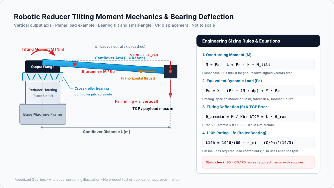
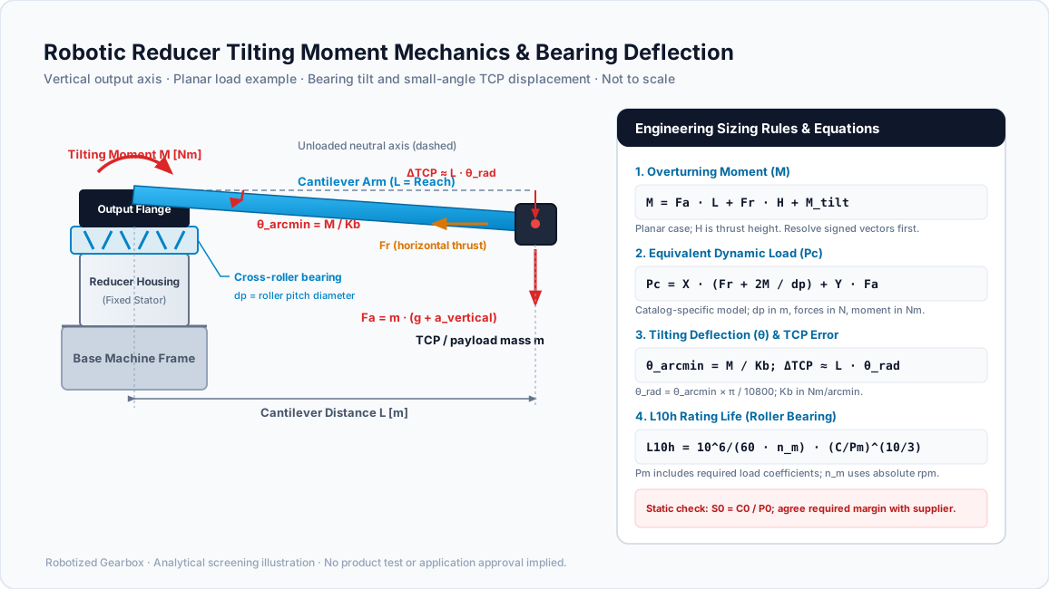
Original schematic, not to scale: the illustrated output axis is vertical, so gravity is axial load and horizontal thrust is radial load. The equations describe a simplified planar case; stiffness and life require the qualifications below.
Resolve each load in the local bearing coordinates first. The moment vector is the sum of force moments (r × F) and applied couples. Only the components perpendicular to the output axis produce tilting; the component around that axis is drive torque. The scalar equations below assume aligned moment contributions with perpendicular lever arms. Combine signed vector components before finding the resultant, and avoid counting the same inertial force twice.
2.1 Static Overturning Moment (M_static)
When the robot link is held stationary in a horizontal cantilever position, gravity acting on the link mass and the end-effector payload generates a sustained static moment:
M_static = (m_arm · L_arm_cg + m_payload · L_payload) · g

Where:
  m_arm         = Mass of the structural robot link [kg]
  L_arm_cg      = Distance from bearing center plane to link center of gravity [m]
  m_payload     = Mass of the end-effector and carried workpiece [kg]
  L_payload     = Distance from bearing center plane to workpiece center of gravity [m]
  g             = Gravitational acceleration (9.81 m/s²)
For a vertical output axis, gravity contributes axial force plus a tilting moment whenever the supported center of mass is offset:
M_static,vert = (m_payload · g) · R_offsetWhere R_offset is the horizontal radial offset from the axis of rotation to the payload center of mass.
2.2 Dynamic Inertial Moment (M_dynamic)
During multi-axis acceleration and deceleration, inertial forces change the bearing moment. The following simplified contributions help build the load model; a multi-axis trajectory may require a rigid-body dynamics calculation.
Linear acceleration force: Use the inertial increment below, then add gravity once when forming the total load. Resolve the direction in the bearing coordinates.
F_dyn = m_payload × a_vertHere a_vert is vertical linear acceleration in m/s^2.
Centrifugal force at an offset: For a mass rotating at radius R_radius, centrifugal force acting at axial height H_offset produces the following simplified bending moment. Gyroscopic couples require a separate inertia-vector calculation.
M_cent = m_payload × ω^2 × R_radius × H_offsetAngular tilting inertia: For angular acceleration about a transverse axis, the simplified inertia moment is below. Acceleration about the output rotation axis instead produces drive torque.
M_rot = J_tilt × α_tiltThe total peak operating tilting moment during normal acceleration is:
M_peak = M_static + M_dynamic + M_process

Where M_process represents external reaction forces (e.g., tool thrust in riveting,
grinding contact force, or resistance welding clamping pressure).
2.3 Emergency Stop (E-Stop) and Shock Overturning Moment (M_emergency)
Stopping loads depend on the controller's stop sequence, brake timing, payload, pose, and stopping distance. Do not infer deceleration or a shock multiplier from the stop category. Obtain the manufacturer's stopping data or validated motion-model results, and calculate coincident radial, axial, and tilting loads during the stop.
Check the resulting peak against the reducer's published maximum moment and combined-load limits. Separately calculate the bearing's static safety factor from static equivalent load. Do not divide an already permissible catalog moment by an arbitrary extra safety factor unless the supplier defines that procedure. A bearing safety factor does not establish collaborative-robot safety or collision safety.
Static load ratings concern a defined contact deformation criterion; they are not a sharp boundary between undamaged operation and immediate failure. Confirm the required margin for precision, shock, and mounting conditions with the supplier.
3. Moment Stiffness (K_b) vs. Torsional Backlash: Calculating Angular Deflection and TCP Droop
Many procurement specifications focus entirely on gear backlash (e.g., <1.0 arcmin) while omitting moment stiffness (K_b, also denoted as K_m or moment rigidity). This is a critical engineering blind spot.
3.1 Understanding the Difference Between Backlash and Tilting
- Torsional Backlash & Lost Motion: Both are evaluated around the output rotation axis. Backlash is clearance-related free play; lost motion is a specified reversal response that can also include elastic deformation and hysteresis. Neither is a transverse moment stiffness rating.
- Moment Stiffness (
K_b): Measured in the perpendicular tilting planes (X-axis andY-axis). It represents the angular slope (θ) caused by an external overturning moment (M). It is expressed in units ofNm/arcmin(orkNm/mrad).
                   Z (Rotation Axis / Torsional Backlash)
                   ▲
                   │
                   │
                   ├───► Y (Tilting Axis, Moment My)
                  ╱
                 ╱
                ▼ X (Tilting Axis, Moment Mx)
The angular tilting deflection (θ) of the output flange under moment M is defined as:
θ = M / K_b  [arcmin]

In radians:
θ_rad = θ · (π / (180 · 60)) = θ · 2.908882 · 10⁻⁴
3.2 Tool Center Point (TCP) Linear Deflection
At the end of a robot link of reach length L_reach, the angular tilt θ creates a direct linear displacement (Δ_TCP) at the tool tip:
Δ_TCP = L_reach · sin(θ_rad) ≈ L_reach · θ_rad [meters]Worked Engineering Comparison:
The following stiffness values are hypothetical inputs, not catalog ratings for named products or measured test results. Assume small angles, a rigid link, and one tilting joint. Consider a robotic dispensing arm with a reach L = 1.2 m carrying an end-effector that applies an overturning moment M = 350 Nm at the shoulder joint during a dispensing pass.
-
Option A (Lower-Stiffness Candidate):
- Assumed Moment Stiffness:
K_b = 280 Nm/arcmin - Angular Tilt:
θ = 350 / 280 = 1.25 arcmin = 3.636 × 10^-4 rad - Linear TCP Deflection:
Δ_TCP = 1.2 m × 3.636 × 10^-4 rad = 0.436 mm(436 µm)
- Assumed Moment Stiffness:
-
Option B (Higher-Stiffness Candidate):
- Assumed Moment Stiffness:
K_b = 1,400 Nm/arcmin - Angular Tilt:
θ = 350 / 1400 = 0.25 arcmin = 7.272 × 10^-5 rad - Linear TCP Deflection:
Δ_TCP = 1.2 m × 7.272 × 10^-5 rad = 0.087 mm(87 µm)
- Assumed Moment Stiffness:
For an allocated bearing-tilt error budget of 0.10 mm, Option A exceeds the budget and Option B leaves only about 0.013 mm for other errors if that is also the total process budget. Neither result approves a complete robot. The buyer should request minimum guaranteed stiffness over the relevant load range and include the other joints and structures in the error allocation.
If bearing tilt consumes your error budget, share the required stiffness, load envelope, and mounting constraints for a sizing review before choosing a larger reducer or adding an external support.
4. Cross-Roller Bearings (CRB) vs. Angular Contact Pairs: Internal Kinematics and Load Capacities
To support heavy overturning moments in a compact axial footprint, modern robotic reducers employ specific internal bearing arrangements. Sourcing engineers must understand the mechanical trade-offs between these designs:
| Bearing architecture | Engineering trade-off | What to request before sourcing |
|---|---|---|
| Integrated cross-roller ring | Supports radial, axial, and moment loads in a compact axial envelope; sensitive to mounting distortion | Bearing pitch diameter, combined-load method, minimum moment stiffness, and mounted friction torque |
| Back-to-back angular contact ball pair | Moment performance depends on row spacing, contact angle, and preload | Bearing span, preload method, fit limits, and stiffness curve |
| Back-to-back tapered roller pair | Can support substantial combined loads; adjustment and friction affect operation | Endplay or preload setting, lubrication requirements, and thermal assessment |
| Spaced deep-groove or thin-section supports | Capacity depends strongly on separation and host structure; component sets require a support design | Complete bearing arrangement, load sharing, housing stiffness, and axial constraint |
| Four-point contact ball bearing | Compact combined-load support; compare the specific size and operating clearance | Moment rating, load interaction limits, and accuracy under operating load |
| External outrigger support | May reduce reducer bending by sharing loads; alignment and thermal constraints become critical | System free-body diagram, support reactions, fit strategy, and alignment tolerance |
Why the Cross-Roller Bearing Dominates Robot Output Stages
A single cross-roller bearing accomplishes what traditionally required a pair of spaced angular contact bearings. Because adjacent cylindrical rollers are crossed at 90° angles, one set of rollers reacts axial load and tilting moment in one direction, while the alternating rollers react loads in the opposite direction.
The roller arrangement provides a compact route to combined-load support. THK’s cross-roller ring introduction illustrates the geometry and a specific rigidity comparison on pages A18-2 to A18-4. It does not establish a universal stiffness multiplier across reducer architectures. Compare mounted stiffness, bearing diameter, preload, and housing conditions for the actual candidates.
5. Step-by-Step ISO 281 Rating Life Calculation for Integrated Output Bearings
Procurement teams frequently encounter catalog claims such as "Rated Bearing Life: 20,000 Hours". Without verifying the load conditions, output speed, and equivalent dynamic load (P_c), such claims are meaningless.
The following method separates basic rating-life arithmetic from model-specific bearing-load conversion. Harmonic Drive’s reducer catalog, engineering pages 30–34, provides an example of the required moment, fatigue, oscillation, and static checks. Use the selected reducer’s own procedure for final approval, especially for cycloidal units with a different main-bearing arrangement.
Step 1: Establish the Operating Mission Profile
Divide the robot's cycle into discrete operating segments i = 1, 2, …, k (e.g., Acceleration, Constant Speed Move, Deceleration, Dwell). For each segment, record:
- Radial force:
F_r,i[N] - Axial force:
F_a,i[N] - Overturning moment:
M_i[Nm] - Mean absolute output speed:
n_i[rpm]; subdivide changing-speed segments so load and speed remain representative - Time duration percentage:
q_i = (t_i / t_total) × 100%
Step 2: Compute Equivalent Dynamic Radial Load (P_c) for Each Segment
For the cross-roller arrangement described in the Harmonic Drive catalog, the following form converts combined loading into a radial equivalent. This is a manufacturer-specific screening model, not a universal equation for every integrated bearing:
P_c,i = X · (F_r,i + (2 · M_i / d_p)) + Y · F_a,i

Where:
  d_p   = Pitch circle diameter of the cross-roller bearing elements [meters]
  M_i   = Applied tilting moment [Nm]
  F_r,i = Applied radial force [N]
  F_a,i = Applied axial force [N]
  X     = Dynamic radial load factor
  Y     = Dynamic axial load factor
The term (2 × M_i / d_p) represents the equivalent radial force couple generated by the overturning moment acting across the roller pitch circle.
Example Catalog Factors, Not Universal ISO Factors
Harmonic Drive’s page 31 gives the following branches for its cross-roller load model. Apply them only to the corresponding bearing arrangement and definitions. All force and moment inputs in this scalar equivalent-load step are magnitudes after vector resolution:
Condition A: If (F_a,i / (F_r,i + 2 · M_i / d_p)) ≤ 1.5:
  X = 1.0
  Y = 0.45

Condition B: If (F_a,i / (F_r,i + 2 · M_i / d_p)) > 1.5:
  X = 0.67
  Y = 0.67
If the denominator is zero with positive axial force, use the axial-dominant branch; if all loads are zero, the equivalent load is zero. Confirm these limits and the supplier’s required load coefficient before accepting a quotation.
Step 3: Calculate the Speed-Weighted Mean Dynamic Load (P_m) and Mean Speed (n_m)
For a piecewise-constant profile, combine fatigue contributions by output revolutions rather than averaging signed speed. Let P_eff,i = f_w,i × P_c,i, where f_w,i is any required manufacturer load coefficient for the segment. It is not a functional safety factor. The Harmonic Drive example includes this coefficient on page 32; omitting a required coefficient overestimates life. The following damage-equivalent mean is an analytical screening calculation, rather than a reproduction of that catalog’s average-force worksheet:
n_m = Σ (n_i · q_i) / 100  [rpm]

For roller bearings (ISO 281 exponent p = 10/3 = 3.333):
P_m = [ Σ (n_i · q_i · P_eff,i^(10/3)) / (100 · n_m) ]^(3/10)  [N]
For ball bearings use exponent p = 3 in the corresponding generalized mean. The time shares must sum to 100%. Reversals do not cancel revolutions. If the mean speed is zero, the hours formula is undefined; perform static and fretting checks instead. Dwell adds no revolutions in this simplified fatigue model, but still requires holding-load and lubrication checks. Small-angle oscillation needs the manufacturer’s oscillation method and lubrication assessment, not an assumption of unlimited life.
Step 4: Calculate the Basic Rating Life (L_10h)
Basic rating life corresponds to 90% reliability against rolling-contact fatigue under its stated assumptions. ISO 281:2007 distinguishes this from modified rating life and excludes wear, corrosion, and electrical erosion. Using the effective mean load above, the basic hours calculation is:
L_10h = (10^6 / (60 · n_m)) · (C / P_m)^p  [hours]

Where:
  C   = Basic dynamic load rating of the integrated bearing [N]
        (From manufacturer catalog)
  P_m = Equivalent dynamic mean load [N]
  n_m = Mean output speed [rpm]
  p   = 10/3 (3.333) for cross-roller / cylindrical roller bearings
  p   = 3.0 for ball bearings
Step 5: Check the Static Safety Factor (S_0) Under Peak Moment
Evaluate each peak event with its coincident radial, axial, and moment loads. For the Harmonic Drive cross-roller model on engineering page 34:
P_0 = F_r + (2 · M / d_p) + 0.44 · F_a  [N]
S_0 = C_0 / P_0
Here C_0 is the catalog basic static load rating in N. That catalog gives example minimum factors of 1.5 for normal conditions, 2 where shock and vibration are expected, and 3 where high rotational precision is required. These are source-specific selection guidelines, not a universal E-stop requirement or a human-safety certification. Verify the applicable criterion with the supplier and independently check its maximum permitted moment.
Illustrative Fatigue Calculation: Why a Short Loaded Move Matters
Assume a hypothetical roller bearing with C = 10,000 N. A cycle spends 20% of its time at 10 rpm with P_eff = 5,000 N, 30% at 20 rpm with P_eff = 2,000 N, and 50% dwelling. These are invented calculation inputs, not a supplier rating or field-life result.
The mean absolute speed is 0.20 × 10 + 0.30 × 20 = 8 rpm. The revolution-weighted mean load is approximately 3,432 N, giving basic life of about 73,600 hours under the stated assumptions. The slower loaded move contributes about 88% of the fatigue-load sum even though it occupies only 20% of cycle time. A time-average force would hide that contribution.
This result is not a maintenance interval. Change the effective load, required coefficient, lubrication assumption, or oscillation pattern and the estimate changes. Also check reducer gear, input-bearing, seal, and grease limits separately. For example, doubling all effective roller loads reduces basic life to about 9.9% of its previous value, with speed unchanged.
6. Bearing Preload Classes, Rolling Friction, and Thermal Seizure Risks in Enclosed Robot Joints
Preload reduces internal clearance and can increase moment stiffness. It also changes starting torque, rolling friction, and sensitivity to mounting distortion. Clearance and preload codes are manufacturer- and size-specific: labels such as C0 or V1 cannot be treated as interchangeable across catalogs.
6.1 Specify the Operating Condition Rather Than a Generic Class
Request the supplier’s clearance or preload definition, inspection temperature, friction-torque acceptance range, and mounting fits. Ask whether stiffness is a nominal reference or a guaranteed minimum. The bearing can operate at a different preload after installation because ring distortion, interference fits, and bolt clamping alter its geometry.
For a precision axis, compare two candidate preload settings against both the TCP error allocation and motor friction allowance. A setting with greater nominal stiffness may require more motor torque or produce more heat. Do not assign a universal percentage increase in friction, a speed ceiling, or a duty-cycle limit without model-specific evidence.
6.2 Temperature and Enclosed Joint Housings
Frictional heating power is approximately T_friction × ω_output in watts when angular velocity is in rad/s. Heat flow through the rings, housing, and adjoining links affects operating clearance. Depending on materials, fits, and thermal gradients, clearance can decrease or increase; thermal runaway is a possible failure mechanism rather than an inevitable sequence.
Request a continuous-duty thermal assessment at the intended ambient temperature, speed, lubrication, and cooling conditions. Compare the stabilized temperatures and starting torque with the manufacturer’s limits. Use warm-up and cool-down measurements to distinguish a reversible thermal change from assembly distortion. A single generic housing-temperature limit cannot approve every bearing, grease, and seal combination.
7. Structural Integration and Mounting Flange Tolerances
Unlike thick-walled traditional bearing assemblies, the outer and inner rings of cross-roller bearings integrated into robot reducers are slender to minimize mass and diameter. When bolted into the robot chassis, the bearing rings conform directly to the geometric accuracy of the mating surfaces.
Mounting face waviness, burrs, or incorrect interference can distort thin rings and create tight spots or torque ripple. The acceptable geometry depends on the bearing size, housing stiffness, fits, and clamp arrangement. Use the approved reducer interface drawing rather than transferring a tolerance from another frame size.
| Interface control | Evidence to request |
|---|---|
| Mounting face flatness | Drawing tolerance, measurement datum, and inspection record |
| Face perpendicularity | Relationship to the bearing axis and permissible assembled tilt |
| Pilot fit and runout | Diameter tolerance, temperature basis, and concentricity requirement |
| Surface finish and cleanliness | Supplier finish specification and burr-removal procedure |
| Fasteners and engagement | Approved grade, thread engagement, torque, and lubrication condition |
| Tightening sequence | Supplier sequence, staged passes, and post-assembly torque check |
Measure unloaded turning torque before and after mounting, using the same temperature and measurement method. If mounting changes torque or produces localized resistance, inspect the interfaces and fits before commissioning. Follow the supplier’s tightening sequence; do not attempt to correct ring distortion by tightening selected bolts beyond their specified torque.
8. Sourcing and Engineering RFQ Checklist
When issuing a Request for Quotation (RFQ) for robot joint reducers, do not simply send target torque and ratio. Use the following 10-point checklist to ensure all suppliers quote models that satisfy actual structural moment requirements:
- 1. Overturning Moment Envelope: Supply the complete moment profile, including static holding moment (
M_static), normal acceleration peak (M_peak), and maximum emergency stop shock (M_emergency) in Nm. - 2. Combined External Forces: List coincident radial force (
F_r) and axial thrust (F_a) acting on the output flange for each phase of the motion profile. - 3. Moment Stiffness Target (
K_b): Define the minimum acceptable moment stiffness inNm/arcminbased on your allowable Tool Center Point (TCP) deflection budget. - 4. Bearing Fatigue Life Expectancy (
L_10h): Specify the target service life (e.g.,L_10h ≥ 20,000hours) along with the duty cycle percentages (q_i) and output speed (n_i). - 5. Static Safety Factor (
S_0): Require a static equivalent-load calculation for each peak event and written agreement on the supplier’s required safety factor and separate maximum moment limit. - 6. Bearing Preload Specification: Agree on the manufacturer’s clearance/preload definition, mounted friction-torque range, and operating temperature limits.
- 7. Mating Interface Drawing: Share CAD boundary files showing housing piloting diameters, bolt circle diameters (PCD), and bolt thread engagement depths.
- 8. Lubrication Compatibility: Confirm factory grease brand, fill quantity, and whether the integrated cross-roller bearing shares the main gearbox lubricant cavity or has a segregated seal chamber.
- 9. Runout Inspection Reports: Request factory lot inspection certificates documenting output flange axial runout, radial runout, and starting friction torque.
- 10. Drop-in Interchangeability Verification: If sourcing an alternative to Nabtesco RV or Harmonic Drive units, verify the complete interface, input connection, ratio, stiffness, accuracy, lubrication, and operating limits. Matching bolt holes or bearing pitch diameter alone does not establish interchangeability.
Use the Gearbox Sizing and Service Factor Calculator for initial ratio and service factor screening, review our RV Speed Reducers for heavy moment applications, or send your completed RFQ moment worksheet to our engineering team.
9. Frequently Asked Questions
What is the practical difference between allowable moment (M_c) and permissible static moment (M_0)?
Catalog terminology varies. In Harmonic Drive’s cited catalog, M_c limits the maximum applied moment; bearing life and static safety factor are then checked separately. Another supplier may define a moment rating at a stated speed and life. Ask for the definition, combined-load conditions, and reference life instead of assuming a fixed ratio between static and operating ratings.
Why do some manufacturers quote moment stiffness in Nm/arcmin while others use kNm/mrad?
Both describe moment divided by angle. One milliradian is approximately 3.43775 arcminutes, so:
1 kNm/mrad = 1000 / 3.43775 ≈ 290.888 Nm/arcmin
1 Nm/arcmin ≈ 0.00343775 kNm/mrad
Check prefixes as well as angle units. Confusing radians with milliradians introduces a factor-of-1,000 error. Always convert ratings to the same units before comparing proposals.
Can an external outrigger bearing double the moment capacity?
An external support may reduce the reducer’s bending load, but there is no automatic doubling rule. Bearing spacing, frame stiffness, load position, alignment, and axial constraints determine the reactions. Calculate the complete support system and agree on an alignment and thermal-expansion strategy with both suppliers. An overconstrained arrangement can introduce parasitic loads.
How does high operating temperature affect cross-roller bearing life?
Higher temperature generally lowers lubricant base-oil viscosity and can reduce film thickness. The resulting lubrication condition depends on speed, load, surface finish, and the chosen lubricant. Temperature also changes ring and housing dimensions: different expansion rates and thermal gradients can loosen a fit or increase constraint. Check operating clearance and lubricant limits for the selected assembly rather than applying a universal temperature-to-life rule.
Does a zero-backlash harmonic drive eliminate tool center point (TCP) vibration?
No. Zero nominal backlash does not eliminate elastic deformation, hysteresis, or transverse bearing tilt. Tool vibration also depends on link stiffness, payload inertia, mounting, and controller tuning. Neither a backlash number nor a reducer architecture alone establishes the robot’s settling time or vibration frequency.
When should a robot designer choose an RV cycloidal reducer over a harmonic drive based on moment load?
Compare actual candidates at the required envelope, mass, speed, stiffness, and combined-load duty. Heavy shoulder joints and positioners often justify evaluating cycloidal units; lightweight wrists may favor strain wave designs. There is no universal 500 Nm crossover. A larger bearing diameter or different support arrangement may matter more than the gear principle.
What causes a cross-roller bearing to exhibit uneven starting torque after assembly?
Possible causes to investigate include:
- Mounting surface flatness outside the selected supplier’s drawing tolerance.
- Debris or burrs trapped between the bearing ring and the mating face.
- Over-torqued or unevenly tightened mounting bolts.
- Excessive interference fit on the housing pilot register warping the outer ring.
Can standard NLGI 2 general-purpose industrial grease be used in the integrated bearing?
The NLGI number describes consistency, not complete lubricant suitability. Use the specific manufacturer-approved lubricant, fill quantity, and relubrication procedure for the bearing and gear cavities. Confirm base oil, thickener compatibility, temperature, seals, and oscillatory operation before substituting a grease or mixing products.
10. Next Steps for a Defensible Reducer Selection
Achieving a reliable, high-precision robot joint requires treating the speed reducer as a structural bearing pivot rather than an isolated gearbox. Sizing must account for cantilever moment arms, dynamic trajectory acceleration, emergency stop deceleration spikes, and structural mounting tolerances.
Before issuing purchase orders, require competing suppliers to submit a formal Application Load Calculation Sheet demonstrating:
- Calculated equivalent dynamic load (
P_c) and speed-weighted load (P_m). - Stated basic rating life (
L_10h) under your specific mission profile. - Static safety factor (
S_0) under emergency stop deceleration. - Bearing-tilt contribution to TCP deflection, with a separate budget for other joints, links, and interfaces.
Contact Robotized Gearbox engineering support to submit your robot kinematic geometry, payload specs, and duty profile for an engineering application review, or compare our RV speed reducer range before requesting an application-specific replacement review.
Sources / References
Source review: November 9, 2026. The sources below support the stated bearing concepts and methods. Hypothetical examples are identified in the text; no customer trials or measured product comparisons are claimed. Confirm the revision and selected-model requirements at quotation, and review this guide when the cited catalog or applicable standard changes.
- Harmonic Drive LLC: Reducer Catalog, engineering pages 30–34: output-bearing moment checks, cross-roller equivalent-load factors, fatigue and oscillation methods, load coefficients, and static checks. These procedures apply to the corresponding catalog arrangements.
- THK Co., Ltd.: Features of the Cross-Roller Ring, pages A18-2 to A18-4: roller arrangement, combined-load support, and a specific rigidity illustration. This introduction does not provide universal preload or machining tolerances.
- ISO: ISO 281:2007 — Rolling bearings: Dynamic load ratings and rating life. The public record explains the basic-life reliability basis, modified-life scope, and exclusions; selected-model coefficients and mounting limits come from the manufacturer.
Author

Categories
M_static)2.2 Dynamic Inertial Moment (M_dynamic)2.3 Emergency Stop (E-Stop) and Shock Overturning Moment (M_emergency)3. Moment Stiffness (K_b) vs. Torsional Backlash: Calculating Angular Deflection and TCP Droop3.1 Understanding the Difference Between Backlash and Tilting3.2 Tool Center Point (TCP) Linear DeflectionWorked Engineering Comparison:4. Cross-Roller Bearings (CRB) vs. Angular Contact Pairs: Internal Kinematics and Load CapacitiesWhy the Cross-Roller Bearing Dominates Robot Output Stages5. Step-by-Step ISO 281 Rating Life Calculation for Integrated Output BearingsStep 1: Establish the Operating Mission ProfileStep 2: Compute Equivalent Dynamic Radial Load (P_c) for Each SegmentExample Catalog Factors, Not Universal ISO FactorsStep 3: Calculate the Speed-Weighted Mean Dynamic Load (P_m) and Mean Speed (n_m)Step 4: Calculate the Basic Rating Life (L_10h)Step 5: Check the Static Safety Factor (S_0) Under Peak MomentIllustrative Fatigue Calculation: Why a Short Loaded Move Matters6. Bearing Preload Classes, Rolling Friction, and Thermal Seizure Risks in Enclosed Robot Joints6.1 Specify the Operating Condition Rather Than a Generic Class6.2 Temperature and Enclosed Joint Housings7. Structural Integration and Mounting Flange Tolerances8. Sourcing and Engineering RFQ Checklist9. Frequently Asked QuestionsWhat is the practical difference between allowable moment (M_c) and permissible static moment (M_0)?Why do some manufacturers quote moment stiffness in Nm/arcmin while others use kNm/mrad?Can an external outrigger bearing double the moment capacity?How does high operating temperature affect cross-roller bearing life?Does a zero-backlash harmonic drive eliminate tool center point (TCP) vibration?When should a robot designer choose an RV cycloidal reducer over a harmonic drive based on moment load?What causes a cross-roller bearing to exhibit uneven starting torque after assembly?Can standard NLGI 2 general-purpose industrial grease be used in the integrated bearing?10. Next Steps for a Defensible Reducer SelectionSources / ReferencesMore Posts
Preventing Thermal Failure in AGV and AMR Drive Gearboxes: A Sourcing Guide
Why compact AGV wheel gearboxes fail from heat before they fail from load, and how procurement and engineering teams can specify thermal limits correctly.
Lost Motion vs. Backlash in Robotic Gearboxes: How Sourcing Teams Read Hysteresis Curves and Prevent Position Drift
Lost motion vs. backlash in robotic gearboxes: read hysteresis curves, estimate tool-tip error, and use an RFQ checklist to request comparable supplier test data.
Harmonic Drive Ratcheting and Flexspline Fatigue: How Sourcing Engineers Size Strain Wave Reducers for Peak Torque and Lifespan
Review harmonic drive ratcheting, flexspline fatigue, peak torque limits, and bearing-life calculations. Prepare a strain wave reducer RFQ with our checklist.